Make a solar cell in your kitchen
A solar cell is a device for converting energy from
the sun into electricity. The high-efficiency solar
cells you can buy at Radio Shack and other stores are
made from highly processed silicon, and require huge
factories, high temperatures, vacuum equipment, and
lots of money.
If we are willing to sacrifice efficiency for the ability
to make our own solar cells in the kitchen out of materials
from the neighborhood hardware store, we can demonstrate
a working solar cell in about an hour.
Our solar cell is made from
cuprous oxide instead of
silicon. Cuprous oxide is one of the first materials known
to display the
photoelectric effect, in which light
causes electricity to flow in a material.
Thinking about how to explain the photoelectric effect is
what led Albert Einstein to the Nobel prize for physics,
and to the theory of relativity.
Materials you will need
The solar cell is made from these materials:
- A sheet of copper flashing from the hardware store.
This normally costs about $5.00 per square foot.
We will need about half a square foot.
- Two alligator clip leads.
- A sensitive micro-ammeter that can read currents
between 10 and 50 microamperes. Radio Shack sells
small LCD multimeters that will do, but I used a
small surplus meter with a needle.
- An electric stove. My kitchen stove is gas, so I bought
a small one-burner electric hotplate for about $25. The
little 700 watt burners probably won't work -- mine is
1100 watts, so the burner gets red hot.
- A large clear plastic bottle off of which you can cut the top.
I used a 2 liter spring water bottle. A large mouth glass
jar will also work.
- Table salt. We will want a couple tablespoons of salt.
- Tap water.
- Sand paper or a wire brush on an electric drill.
- Sheet metal shears for cutting the copper sheet.
How to build the solar cell
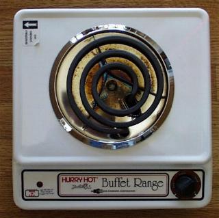
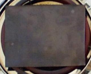
My burner looks like this:
The first step is to cut a piece of the copper sheeting
that is about the size of the burner on the stove. Wash your
hands so they don't have any grease or oil on them. Then
wash the copper sheet with soap or cleanser to get any oil
or grease off of it.
Use the sandpaper or wire brush to thoroughly clean the copper
sheeting, so that any sulphide or other light corrosion is
removed.
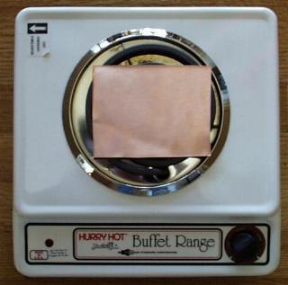
Next, place the cleaned and dried copper sheet on the burner
and turn the burner to its highest setting.
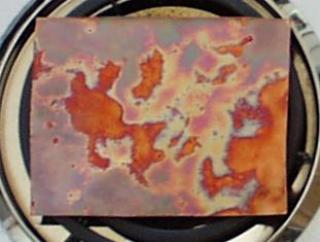
As the copper starts to heat up, you will see beautiful oxidation
patterns begin to form. Oranges, purples, and reds will cover the
copper.
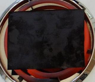
As the copper gets hotter, the colors are replaced with a black
coating of
cupric oxide. This is
not the oxide
we want, but it will flake off later, showing the reds, oranges,
pinks, and purples of the cuprous oxide layer underneath.
The last bits of color disappear as the burner starts to glow red.
When the burner is glowing red-hot, the sheet of copper will be
coated with a black cupric oxide coat. Let it cook for a half
an hour, so the black coating will be thick. This is important,
since a thick coating will flake off nicely, while a thin coat
will stay stuck to the copper.
After the half hour of cooking, turn off the burner.
Leave the hot copper on the burner to cool slowly.
If you cool it too quickly, the black oxide will stay
stuck to the copper.
As the copper cools, it shrinks.
The black cupric oxide also shrinks.
But they shrink at different rates, which makes
the black cupric oxide flake off.
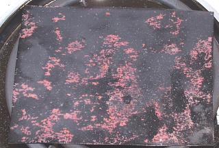
The little black flakes pop off the copper with
enough force to make them fly a few inches. This
means a little more cleaning effort around the stove,
but it is fun to watch.
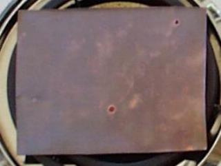
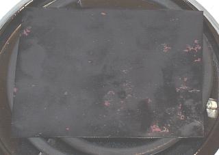
When the copper has cooled to room temperature (this takes about
20 minutes), most of the black oxide will be gone. A light scrubbing
with your hands under running water will remove most of the small
bits. Resist the temptation to remove all of the black spots by
hard scrubbing or by flexing the soft copper. This might damage
the delicate red cuprous oxide layer we need to make to solar cell work.
The rest of the assembly is very simple and quick.
Cut another sheet of copper about the same size as the first one.
Bend both pieces gently, so they will fit into the plastic bottle
or jar without touching one another. The cuprous oxide coating
that was facing up on the burner is usually the best side to face
outwards in the jar, because it has the smoothest, cleanest surface.
Attach the two alligator clip leads, one to the new copper plate,
and one to the cuprous oxide coated plate. Connect the lead from
the clean copper plate to the positive terminal of the meter.
Connect the lead from the cuprous oxide plate to the negative
terminal of the meter.
Now mix a couple tablespoons of salt into some hot tap water.
Stir the saltwater until all the salt is dissolved.
Then carefully pour the saltwater into the jar, being careful not
to get the clip leads wet. The saltwater should not completely
cover the plates -- you should leave about an inch of plate
above the water, so you can move the solar cell around without
getting the clip leads wet.
The photo above shows the solar cell in my shadow as I took
the picture. Notice that the meter is reading about 6 microamps
of current.
The solar cell is a battery, even in the dark, and will usually
show a few microamps of current.
The above photo shows the solar cell in the sunshine.
Notice that the meter has jumped up to about 33 microamps
of current. Sometimes it will go over 50 microamps, swinging
the needle all the way over to the right.
How does it do that?
Cuprous oxide is a type of material called a
semiconductor.
A semiconductor is in between a conductor, where electricity can
flow freely, and an insulator, where electrons are bound tightly
to their atoms and do not flow freely.
In a semiconductor, there is a gap, called a
bandgap between
the electrons that are bound tightly to the atom, and the electrons
that are farther from the atom, which can move freely and conduct
electricity.
Electrons cannot stay inside the bandgap. An electron cannot gain
just a little bit of energy and move away from the atom's nucleus
into the bandgap. An electron must gain enough energy to move
farther away from the nucleus, outside of the bandgap.
Similarly, an electron outside the bandgap cannot lose a little
bit of energy and fall just a little bit closer to the nucleus.
It must lose enough energy to fall past the bandgap into the
area where electrons are allowed.
When sunlight hits the electrons in the cuprous oxide, some of the
electrons gain enough energy from the sunlight to jump past the bandgap
and become free to conduct electricity.
The free electrons move into the saltwater, then into the clean copper plate,
into the wire, through the meter, and back to the cuprous oxide plate.
As the electrons move through the meter, they perform the work needed to
move the needle. When a shadow falls on the solar cell, fewer electrons
move through the meter, and the needle dips back down.


